RoboRat
Robutek II is still alive
Two years ago I published an article about creation of my robot Robutek II. I also promissed some kind of “open-end” series, but unfortunately only the first article was written. The good news is that I had more time for playing, so there are many new things on the robot. Are you still interested in what happened with Robutek II?
Historic context
Two years ago I published an article about creation of my robot Robutek
II. I also promised some kind of “open-end” series, but unfortunately only
the first article was written. The good news is that I had at least more time
for playing, so there are many new things on the robot. There are actually
some stories on robotika.cz revealing some of her history. For example in
the robotics diary of the team
Short Circuits Prague (Eurobot 2004 contest). The robot appeared under
nickname “RoboRat”. Because we got used to this name, I will use it in this
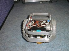
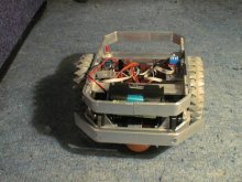
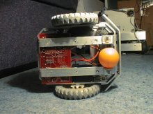
article too. This nickname RoboRat comes from its current job. It works as an
assistant robot for experiments with teaching rats in the Institute of
Physiology, Academy of Science. It works there for the second year already.
In one test robot behaves as a predator placed in circular arena with
diameter 1m together with rat, whose task is to avoid robot in safe distance.
RoboRat does not see the rat. It has very simple strategy: it moves straight
until it hits wall with active bumper, backs up, turns in place for random
angle and moves forward again. The task of RoboRat is not as much interesting
as the conditions under which it has to do the job. RoboRat works in very dirty
environment (rats do not take any respect to small robots). Also there is no
technically experienced operator who could immediately fix potential problems,
so the robot reliability has to be very high. After several small modifications
from the original design RoboRat could be proud of two years trouble-free
operation. According to the institute test data it traveled more than 7km with
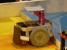
three service checks. For it was slightly modified to become a secondary robot. Her main goal
was to act as a moving obstacle and to block the opponent robot. It worked very
well thanks to the tough construction.
Construction
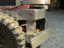
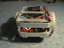
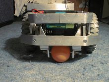
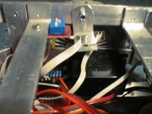
The main structure material for RobotRat are aluminum bands 16mm wide and
3mm thick. According to my experience they are easy to cut, drill or bend. For
the construction of such a small robot they are tough enough. In the original
draft RoboRat parts were linked with screws M3 with threads directly in
aluminum. On several stressed places they had to be replaced with bolts and
nuts (very useful were the ones with plastic fill, which do not get easily
loose any more), because the threads in aluminum were not very lasting.
Drive
The motion subsystem went though the biggest changes. Originally there were
two motors from Merkur (Czech kind of Meccano) – the same as in
Robutek I. It was quite sufficient for the
movement. Also the same tested electronics originally for Robutek I could be
used (H-bridge L293D as a motor controller). Then I got the offer from the
institute, and one of the requirements was different speeds of operation. The
slowest required speed was not obtainable with these motors using PWM
regulation. So I decided to use different motors.
The most affordable motor
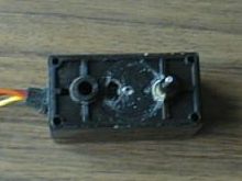
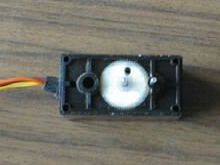
with gear, which is necessary for the slow speeds, is ordinary model servo. I
cut position limits from the last toothed wheel and I fixed potentiometer so it
does not move together with the wheel any more (the potentiometer is used by
servo electronics to measure current wheel orientation). In the new setup, the
servo will never reach desired orientation (potentiometer does not move) and so
it continuously turns.
Another servo feature is that further positions (differences) are realized
with higher speed. So if we fixed potentiometer in the approximate center
position, we can control speed and direction with standard servo signal. So if
we use 8bit resolution for the signal (values 0 to 255), servo will turn in one
direction for values smaller than 128 and in the other direction for greater
values. The absolute difference from 128 defines speed. In the ideal world
would servo stop for value equal to 128 – the trick how to get close to this is
to set output signal to value 128 and then turn potentiometer until servo does
not move. In the real world this value changes depending on batery level and
so it is better to stop servo simply with not sending any signal.
Board
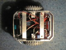
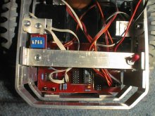
RoboRat is controlled by microchip Atmel AVR AT90S4433. The board has
connector for serial communication UART, ISP programming connector, digital and
analog I/Os and connectors for servos and encoders. The board also contains
comparator LM393 with trims for digitalization of analog signals from encoders.
Encoders
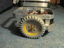
Encoders are the second part with the biggest changes in RoboRat evolution.
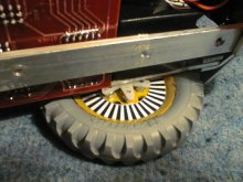
Originally I used proved configuration where IR-LED with phototransistor
(CNY70) scans robot wheel with black and white strips. This solution worked
fine in normal circumstances. Unfortunately in very dirty environment it
quickly lost original reflective property. Another problem was that experiments
with rats are recorded by IR camera, which was disturbed by these IR sources.
Moreover this setup was very sensitive to mounting and once a while somebody
inexperienced changed mechanics with bad side-effects. This was motivation for
different, more compact and robust, encoders. The final solution was placement
of encoders directly into servo.
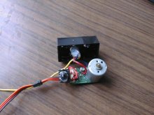
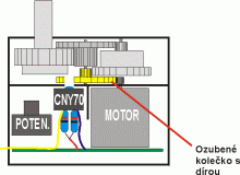
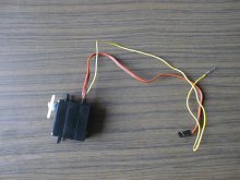
The goal was to place sensor CNY70 into servo and instead of striped wheel
we could use one of toothed wheels. The whole encoder is then safely placed
inside servo and is practically unbreakable, the surrounding does not influence
its behavior and also emitted IR does not influence the environment. For
placement I used space where usually is foam for fixing potentiometer (if
needed, potentiometer axis could be also shorted). This space is sufficient for
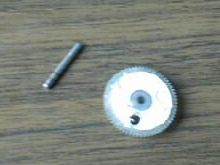
sensor CNY70 and few necessary resistors. I drilled a hole into the very first
toothed wheel near the motor, so the sensor shines through the hole or not. For
better reflectivity I pained bottom part of the wheel with white. I glued
sensor and resistors for better compactness using hot glue. It is important
that the hole is big enough so that both active parts are visible. I could use
power (+5V) and ground from servo board thanks to fact that pull-up resistor
and resistor for powering LED were both placed into the case of servo. So there
is only one extra output cable from servo, which can be connected to analog
input of microchip. Wiring of CNY70 is described in article
Jak programátor k robotovi přišel.
The drawback of this solution is that it is not possible to detect
direction of servo rotation. For this we would need two sensors but they would
not fit into the servo case. In reality it is not a big issue because we
typically know which direction should servo turn and spontaneous motion
is exceptional. Servo motor turns very fast and has high torque. Note, that as
a programmer it is necessary to pay attention at signal oscillations on the
edge of the hole. It could easily cause “virtual” motion of robot. The
resolution of servo is around 100 ticks per revolution due to fact that we use
the fastest moving wheel.
Radio
Another requirement which arose during experiments was speed control (change
speed within 20 minutes testing sessions). It needed wireless solution because
cable would interfere with the experiment setup. The cheapest solution I found
was one-way radio modules RTF-DATA-SAW and TX-SAW from Aurel. They are easy to
buy (in CR you can find them in GES for around 400 Kč total i.e. 14EUR). Using
relatively simple circuit from datasheets for these modules I could create
boards. The transmitter board contains chip AT90S1200 which is connected with
an old joystick. The receiver board is then connected directly to the control
microchip on RoboRat. One timer of RoboRat board is used for signal sampling.
Those two modules do not support any protocol for the data transmission – what
is written to one pin on the first board will show up on another pin of the
second board. Using relatively simple protocol I was able to transmit reliably
data inside room within couple of meters (without any knowledge about antenna
construction and communication media in general…).
 Servo wheel |
 Servo |
 After modification |
Send email to the editors
Your message could not be sent
but you can also reach us at webmaster-at-robotika.cz
Your message was successfully sent.
You need to turn on javascript to submit this form.
