Servo-encoder
odometry sensor for a simple robot
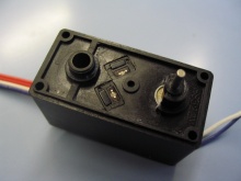
R/C model servos are very popular way to propel small robots. They are relatively cheap and powerful with quality gears and built-in electronics. Unfortunately servo itself does not have any sensor, which would measure how fast it turns. This is the task for optical incremental encoders. In this article we will show a compact solution to incorporate an optical encoder in standard R/C model servo case.
Once we have the information from incremental encoder about
the distance traveled by each wheel, we can easily calculate new robot's position
using odometry and use the robot for more sophisticated missions.
Encoder implementation
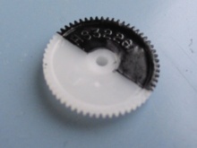 Encoder wheel |
For the first experiment we used sensors from the very affordable PC wheeled
mouse. The encoder wheel replaced the original potentiometer and the double
optical gate was attached to the side of the housing. This solution worked
(and still works after more than 2 years) but the initial setup was very
difficult. Tuning the optical gate placement has turned into a horror :-(.
This led us to a solution that would be easier to replicate.
The idea was taken from Pavel Jiroutek's RoboRat.
It was further extended to yield a proper quadrature signal that provides
also the direction of the rotation. The CNY70 sensors used in the original
RoboRat are to big to fit two of them inside the housing
so we used QRD1114 instead. It is cheaper, smaller and appears to be even more
sensitive than CNY70.
The final solution can be built (with a bit of patience) in an hour and
requires parts for less than 100 Kč (approximately $4). The reward then is this
warm feeling of good work done and a compact propeller with an encoder for your
small robot.
What do we need?
For modification we will use broadly available servo Hitec HS-322.
Other parts:
| IR reflexive photo-gate QRD1114 | 2x |
| resistor miniature - 2k7 | 2x |
| SMD resistor size 1206 - 220ohm | 1x |
| SMD resistor size 1206 - 4k7 | 2x |
| SMD ceramic capacitor size 1206 - 100nF | 1x |
| SMD integrated circuit 74HC14 | 1x |
| four wire cable (the same cross-section like servo cable) | |
| circuit board (it is possible to build it without the board, but the result is less robust) |
Tools:
- soldering iron
- needle-shaped files
- drilling-machine and drill (3-4mm)
- Phillips screwdriver
- pincers
- knife
- brush and black matte color (for example for model kits)
- adhesive tape
Procedure
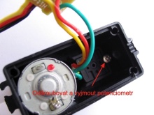
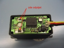
Let's start with the servo disassembly. Unscrew lower cover and unsolder supply for
the motor. Remove control board from the servo — the last servo series were
fixed with some glue, so it may be slightly stiff. Cut-out potentiometer
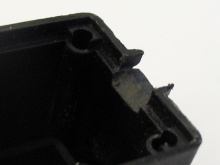
connections and take apart gears. It is necessary to remove/cut small limits
which restricts motion to 180° only. Use pincers and knife for clean cut.
Unscrew potentiometer and pull it out.
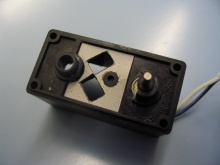
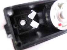
Now we will have to deal with the hardest part, preparation of holes for the
optical sensors. You can use template (print it out with
600 DPI resolution).
Attach template to servo box so that circular whole match axis of the first
gearwheel. Mark the holes. Using adhesive tape protect the motor from the
dust (it is very hard to clean it afterwards). Drill holes to both openings <
4mm and using small file finish desired shape. Test it by placing the sensor.
The next task is to enlarge the hole for the sensor cable. We can use file again to
do it — askew inside file slope.
Finally we have to paint the gearwheel (one half has to be black). Remove all
grease, protect other half with adhesive tape and paint it. We recommend mate
black color for model kits. When wheel gets dry and clean small bits of leaked
color below the tape (you can use a knife).
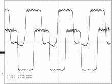
The quality of the signal from sensors was far beyond our expectation (see the
picture from oscilloscope). This means that the outputs could be directly fed
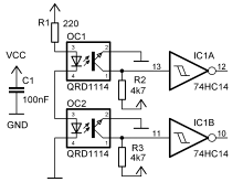
into the chip, but better practice is to filter signals through Smitth trigger.
The values of resistors were selected experimentally.
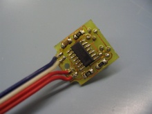
Place resistors, capacitor and integrated circuit on the board.
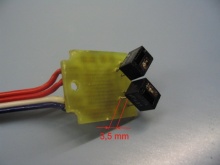
The sensors should be oriented by phototransistor, i.e. darker side out. Solder
them so the upper side would match with the servo surface (see the picture).
Solder sensors with bottom side 3.5mm above the board or rather directly
in the servo. Place and solder DPS (there is not much space, but we can be
sure that sensor will be where we wanted).
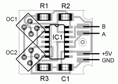 Population of DPS |
It is time to try the sensor. Insert the board into servo with insolating
cover, fasten it with the potentiometer screw. Assemble the gears, connect 5V
and check encoders output. If everything is all right then you should be able
to see desired changes on encoder output. Now we can complete the board:
remove unused cables from potentiometer and replace them by 2k7 resistors.
Encoder cable place to enlarged hole and return control board back to original
place. Solder motor terminals and check encoders again with running motor.
How to control servos you can learn in guide Servo control and
how to evaluate encoder output will be in some future article.
If you found this article interesting, and you would like to add your comment,
or if you found mistakes or inconsistency, please let us know via our
contact form.
Send email to the editors
Your message could not be sent
but you can also reach us at webmaster-at-robotika.cz
Your message was successfully sent.
You need to turn on javascript to submit this form.
